Specifications
- Automotive (Y/N)
- N
- Package
- TO252-3L
- Configuration
- N
- Tj
- 175 °C
- VDS_Max
- 800 V
- ID_Max
- 25 A
- VGS_Max
- -10/+22 V
- VGS(th)_Typ
- 3.2 V
- RDS(ON)_Typ @VGS=18V,25°C
- 125 mΩ
- RDS(ON)_Max @VGS=18V,25°C
- 150 mΩ
- RDS(ON)_Typ @VGS=18V,175°C
- 180 mΩ
- Ciss_Typ
- 706 pF
- Coss_Typ
- 43 pF
- Crss_Typ
- 3 pF
- Qg_Typ
- 29 nC
- MPQ
- 2500 pcs
- MOQ
- 25000 pcs
Not sure how to choose? Read the SiC MOSFETs Selection Guide →
Package & Schematic
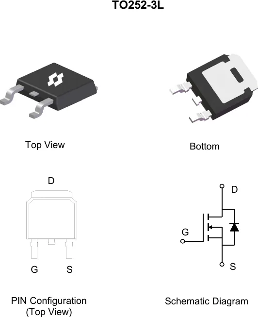 Package outline · Pin configuration · Schematic (from SineSemi official datasheet)
Online Datasheet
Compiled from the manufacturer's datasheet; the official document prevails.
SCMP80R130BU
800V N-Channel Silicon Carbide Power MOSFET
Product Summary
| VDS |
RDS(ON), typ |
ID, max |
| 800 V |
125 mΩ @ VGS = 18V |
25 A |
TO252-3L
Maximum Ratings (@ TC = 25°C, unless otherwise specified.)
| Parameter |
Symbol |
Test Condition |
Value |
Unit |
| Drain - Source Voltage |
VDSmax |
VGS = 0V, ID = 100µA |
800 |
V |
| Gate - Source Voltage |
VGSmax |
Absolute maximum values |
-10/+22 |
V |
| Gate - Source Voltage |
VGSop |
Recommended operating values |
-5/+18 |
V |
| Continuous Drain Current |
ID |
TC = 25°C |
25 |
A |
|
|
TC = 100°C |
17 |
A |
| Junction & Storage Temperature Range |
TJ, TSTG |
— |
-55 ~ +175 |
°C |
Thermal Characteristics
| Parameter |
Symbol |
Typ |
Max |
Unit |
| Thermal Resistance, Junction-to-Ambient |
R_θJA |
30 |
38 |
°C/W |
| Thermal Resistance, Junction-to-Case |
R_θJC |
1.0 |
1.2 |
°C/W |
Electrical Characteristics (@ TJ = 25°C, unless otherwise specified.)
Off Characteristics
| Parameter |
Symbol |
Test Condition |
Min |
Typ |
Max |
Units |
| Drain-Source Breakdown Voltage |
V(BR)DSS |
VGS = 0V, ID = 100µA |
800 |
— |
— |
V |
| Zero Gate Voltage Drain Current |
IDSS |
VDS = 800V, VGS = 0V |
— |
1.0 |
100 |
µA |
| Gate-Source Leakage Current |
IGSS |
VGS = +22V, VDS = 0V |
— |
— |
100 |
nA |
|
|
VGS = -10V, VDS = 0V |
— |
— |
100 |
nA |
On Characteristics
| Parameter |
Symbol |
Test Condition |
Min |
Typ |
Max |
Units |
| Gate Threshold Voltage |
VGS(th) |
VGS = VDS, IDS = 2.5mA, TJ = 25°C |
2.2 |
3.2 |
4.2 |
V |
|
|
VGS = VDS, IDS = 2.5mA, TJ = 175°C |
— |
2.3 |
— |
V |
| Static Drain-Source On-Resistance |
RDS(on) |
VGS = 18V, ID = 10A, TJ = 25°C |
— |
125 |
150 |
mΩ |
|
|
VGS = 18V, ID = 10A, TJ = 175°C |
— |
180 |
— |
mΩ |
|
|
VGS = 15V, ID = 10A, TJ = 25°C |
— |
175 |
— |
mΩ |
|
|
VGS = 15V, ID = 10A, TJ = 175°C |
— |
195 |
— |
mΩ |
|
|
VGS = 12V, ID = 10A, TJ = 25°C |
— |
330 |
— |
mΩ |
|
|
VGS = 12V, ID = 10A, TJ = 175°C |
— |
240 |
— |
mΩ |
| Diode Forward Voltage |
VSD |
VGS = -5.0V, ISD = 5.0A, TJ = 25°C |
— |
3.5 |
— |
V |
|
|
VGS = -5.0V, ISD = 5.0A, TJ = 175°C |
— |
3.2 |
— |
V |
Dynamic Characteristics
| Parameter |
Symbol |
Test Condition |
Min |
Typ |
Max |
Units |
| Input Capacitance |
Ciss |
VDS = 400V, VGS = 0V, f = 1MHz |
— |
706 |
— |
pF |
| Output Capacitance |
Coss |
|
— |
43 |
— |
pF |
| Reverse Transfer Capacitance |
Crss |
|
— |
3.0 |
— |
pF |
| Internal Gate Resistance |
RG(int) |
f = 1MHz, ID = 0A |
— |
13.0 |
— |
Ω |
Switching Characteristics
| Parameter |
Symbol |
Test Condition |
Min |
Typ |
Max |
Units |
| Turn-On Switching Loss |
Eon |
VDS = 400V, VGS = -5/+18V, ID = 10A, RG(ext) = 5.1Ω |
— |
40 |
— |
µJ |
| Turn-Off Switching Loss |
Eoff |
|
— |
18 |
— |
µJ |
| Turn-On Delay Time |
td(on) |
|
— |
6.0 |
— |
ns |
| Rise Time |
tr |
|
— |
14 |
— |
ns |
| Turn-Off Delay Time |
td(off) |
|
— |
10 |
— |
ns |
| Fall Time |
tf |
|
— |
6.0 |
— |
ns |
Gate Charge Characteristics
| Parameter |
Symbol |
Test Condition |
Min |
Typ |
Max |
Units |
| Total Gate Charge |
Qg |
VDS = 400V, VGS = -5/18V, ID = 10A |
— |
29 |
— |
nC |
| Gate-Source Charge |
Qgs |
|
— |
12 |
— |
nC |
| Gate-Drain Charge |
Qgd |
|
— |
4.0 |
— |
nC |
Drain-Source Diode Characteristics
| Parameter |
Symbol |
Test Condition |
Min |
Typ |
Max |
Units |
| Reverse Recovery Time |
trr |
VR = 400V, VGS = -5.0V, ISD = 10A, di/dt = 1000A/µs |
— |
30 |
— |
ns |
| Reverse Recovery Charge |
Qrr |
|
— |
55 |
— |
nC |
| Peak Reverse Recovery Current |
IRRM |
|
— |
3.6 |
— |
A |
| Continuous Diode Forward Current |
IS |
TC = 25°C |
— |
— |
29 |
A |
|
|
TC = 100°C |
— |
— |
17 |
A |
