
Product Detail
SMT4001BHFP5Q
SineSemi 中晶新源Core Authorized Distributor
Specifications
- Package
- LFPAK5060
- Configuration
- N
- VDS_Max
- 40 V
- ID
- 302 A
- RDS(ON)_Max @VGS=10V
- 1 mΩ
- Automotive (Y/N)
- Y
- VGS(th)_Typ
- 3 V
- RDS(ON)_Typ @VGS=10V
- 0.82 mΩ
- VGS_Max
- ±20 V
- Tj
- 175 °C
- EAS_Max
- 672 mJ
- Ciss_Typ
- 4197 pF
- Coss_Typ
- 2504 pF
- Crss_Typ
- 76 pF
- Qg_Typ
- 59 nC
- ESD
- No
- MPQ
- 5000 pcs
- MOQ
- 50000 pcs
- App: Motor Drive
- Y
- App: HF Power
- Y
- App: General Switch
- Y
Not sure how to choose? Read the LV & MV MOSFETs Selection Guide →
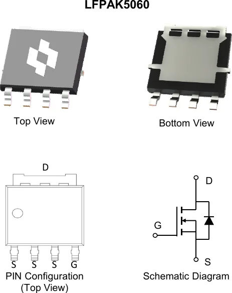
Package & Schematic
Online Datasheet
Compiled from the manufacturer's datasheet; the official document prevails.
SMT4001BHFP5Q
40V N-Channel Power MOSFET
Sinesemi Automotive MOSFET — AEC-Q101 Qualified, 175°C
Product Summary
| VDS | RDS(ON)_TYP | I_D_MAX |
|---|---|---|
| 40 V | 0.82 mΩ @VGS = 10V | 302 A |
LFPAK5060
Features
- N-Channel Enhancement Mode - Standard Level
- AEC-Q101 Qualified, PPAP Capable
- 175°C Operating Temperature
- 100% ΔVDS & UIS & Rg Tested
Applications
- General Automotive Applications
Mechanical Data
- Green Molding Compound
- Moisture Sensitivity: Level 1 per J-STD-020
- UL Flammability Classification Rating 94V-0
Ordering Information
| Orderable Part Number | Package Type | Device Marking | Form | Quantity (pcs) |
|---|---|---|---|---|
| SMT4001BHFP5Q | LFPAK5060 | 4001BHQ | 13" Tape&Reel | 5,000 |
Maximum Ratings (@ TC = 25°C, unless otherwise specified.)
| Parameter | Symbol | Value | Unit |
|---|---|---|---|
| Drain - Source Voltage | VDS | 40 | V |
| Gate - Source Voltage | VGS | ±20 | V |
| Continuous Drain Current (VGS = 10V) (1) | ID @ TC = 25°C | 302 | A |
| ID @ TC = 100°C | 214 | A | |
| Pulsed Drain Current (2) | IDM | 1209 | A |
| Single Pulse Avalanche Energy (3) | EAS | 672 | mJ |
| Single Pulse Avalanche Current (L = 0.1mH) | IAS | 74 | A |
| Power Dissipation | PD @ TC = 25°C | 158 | W |
| PD @ TC = 100°C | 79 | W | |
| Junction & Storage Temperature Range | TJ, TSTG | -55 ~ +175 | °C |
Thermal Characteristics
| Parameter | Symbol | Typ. | Max. | Unit |
|---|---|---|---|---|
| Thermal Resistance, Junction-to-Ambient (4) | R_θJA | 31 | 39 | °C/W |
| Thermal Resistance, Junction-to-Case (5) | R_θJC | 0.73 | 0.95 | °C/W |
Electrical Characteristics (@ TJ = 25°C, unless otherwise specified.)
Off Characteristics (6)
| Parameter | Symbol | Test Condition | Min. | Typ. | Max. | Unit |
|---|---|---|---|---|---|---|
| Drain-Source Breakdown Voltage | V(BR)DSS | VGS = 0V, ID = 250µA | 40 | — | — | V |
| Zero Gate Voltage Drain Current | IDSS | VDS = 40V, VGS = 0V | — | — | 1.0 | µA |
| TJ = 125°C | — | — | 100 | µA | ||
| Gate-Source Leakage Current | IGSS | VGS = ±20V, VDS = 0V | — | — | ±100 | nA |
On Characteristics (6)
| Parameter | Symbol | Test Condition | Min. | Typ. | Max. | Unit |
|---|---|---|---|---|---|---|
| Gate Threshold Voltage | VGS(th) | VGS = VDS, ID = 250µA | 2.0 | 3.0 | 4.0 | V |
| Static Drain-Source On-Resistance | RDS(ON) | VGS = 10V, ID = 20A | — | 0.82 | 1.0 | mΩ |
| Forward Transconductance | gfs | VDS = 5.0V, ID = 20A | — | 53 | — | S |
| Diodes Forward Voltage | VSD | IS = 2.0A, VGS = 0V | — | 0.7 | 1.2 | V |
Dynamic Characteristics (7)
| Parameter | Symbol | Test Condition | Min. | Typ. | Max. | Unit |
|---|---|---|---|---|---|---|
| Input Capacitance | Ciss | — | 4197 | 5456 | pF | |
| Output Capacitance | Coss | VDS = 20V, VGS = 0V, f = 1MHz | — | 2504 | 3255 | pF |
| Reverse Transfer Capacitance | Crss | — | 76 | 152 | pF | |
| Gate Resistance | Rg | VGS = 0V, VDS = 0V, f = 1MHz | — | 1.2 | — | Ω |
Switching Characteristics (7)
| Parameter | Symbol | Test Condition | Min. | Typ. | Max. | Unit |
|---|---|---|---|---|---|---|
| Turn-On Delay Time | td(on) | — | 7.4 | — | ns | |
| Rise Time | tr | VGS = 10V, VDS = 20V | — | 13 | — | ns |
| Turn-Off Delay Time | td(off) | ID = 20A, RGEN = 3.0Ω | — | 29 | — | ns |
| Fall Time | tf | — | 14 | — | ns |
Gate Charge Characteristics (7)
| Parameter | Symbol | Test Condition | Min. | Typ. | Max. | Unit |
|---|---|---|---|---|---|---|
| Total Gate Charge (VGS = 10V) | Qg | — | 59 | 77 | nC | |
| Total Gate Charge (VGS = 7.0V) | Qg | VDS = 20V, ID = 20A | — | 42 | 55 | nC |
| Gate-Source Charge | Qgs | VGS = 10V | — | 17.2 | 26 | nC |
| Gate-Drain Charge | Qgd | — | 11.8 | 17.7 | nC | |
| Gate Plateau Voltage | Vplateau | — | 4.5 | — | V |
Drain-Source Diode Characteristics (7)
| Parameter | Symbol | Test Condition | Min. | Typ. | Max. | Unit |
|---|---|---|---|---|---|---|
| Body Diode Reverse Recovery Time | trr | IF = 20A, dI/dt = 100A/µs, | — | 58 | — | ns |
| Body Diode Reverse Recovery Charge | Qrr | TJ = 25°C | — | 80 | — | nC |
| Diode Forward Current | IS | TC = 25°C | — | — | 302 | A |
Notes:
- This current is chip limited, which is calculated based on Rthjc.
- This current is calculated on single pulse with 10µs Single Pulse.
- Defined by design, not subject to production test, EAS condition: TJ=25°C, VDD=20V, VGS=10V, L=1.0mH.
- Device mounted on FR-4 substrate PC board with 2oz copper in 1inch square cooling area.
- Thermal resistance from junction to the exposed pad.
- Short duration pulse test used to minimize self-heating effect.
- Defined by design, not subject to production.
Typical Electrical and Thermal Characteristics
(曲线图略:Figure 1 Output Characteristics、Figure 3 On-Resistance vs. Gate-Source Voltage、Figure 4 On-Resistance vs. Drain Current and Gate Voltage ×2、Figure 5 On-Resistance vs. Junction Temperature、Figure 6 Source-Drain Diode Forward Voltage、Figure 7 Gate Threshold Variation vs. Junction Temperature、Figure 8 Gate Charge Characteristics、Figure 9 Capacitance Characteristics、Figure 10 Power Derating、Figure 11 Current Derating、Figure 12 Safe Operating Area、Figure 13 Normalized Maximum Transient Thermal Impedance)
Figure 13 说明:
- δ = 0.5, 0.3, 0.1, 0.05, 0.02, 0.01, single pulse
- Duty cycle δ = t1 / t2
- RJC(t) = r(t) × R_θJC
LFPAK5060 Package Outline
Package Outline Dimensions (MILLIMETERS)
| DIM. | MIN. | NOM. | MAX. |
|---|---|---|---|
| A | 1.00 | — | 1.30 |
| A1 | 0.00 | — | 0.15 |
| A2 | 0.98 | 1.03 | 1.10 |
| b | 0.35 | 0.42 | 0.50 |
| b1 | 4.02 | 4.23 | 4.41 |
| c | 0.19 | 0.22 | 0.25 |
| c1 | 0.24 | 0.27 | 0.30 |
| D | 5.10 | — | 5.30 |
| D1 | 4.95 | 5.13 | 5.30 |
| D2 | 3.50 | — | 3.70 |
| E | 5.95 | — | 6.20 |
| E1 | 4.45 | 4.58 | 4.70 |
| E2 | 4.10 | — | 4.45 |
| e | 1.27 BSC. | ||
| L | 0.40 | 0.65 | 0.85 |
| L1 | 0.27 | — | 0.57 |
| L2 | 0.80 | — | 1.30 |
| θ | 0° | — | 8° |
Notes:
- DIMENSIONING AND TOLERANCING PER ASME Y14.5M,1994.
- ALL DIMENSIONS IN MILLIMETER (ANGLE IN DEGREE).
- DIMENSIONS "D1" AND "E1" DO NOT INCLUDE MOLD FLASH PROTRUSIONS OR GATE BURRS.
Recommended Soldering Footprint (DIMENSIONS: MILLIMETERS)
(焊盘图略;关键尺寸:6.600 × 4.800,引脚区 4.784 宽,引脚间距 1.270,引脚宽 1.150,底部退距 0.520)