Specifications
- Package
- PDFN5060-8L
- Configuration
- N
- VDS_Max
- 40 V
- ID
- 180 A
- RDS(ON)_Max @VGS=10V
- 1.8 mΩ
- Automotive (Y/N)
- N
- VGS(th)_Typ
- 3 V
- RDS(ON)_Typ @VGS=10V
- 1.5 mΩ
- VGS_Max
- ±20 V
- Tj
- 150 °C
- EAS_Max
- 436 mJ
- Ciss_Typ
- 2890 pF
- Coss_Typ
- 1682 pF
- Crss_Typ
- 77 pF
- Qg_Typ
- 39 nC
- ESD
- No
- MPQ
- 5000 pcs
- MOQ
- 50000 pcs
- App: Motor Drive
- Y
- App: HF Power
- Y
- App: Battery Protection
- Y
- App: General Switch
- Y
Not sure how to choose? Read the LV & MV MOSFETs Selection Guide →
Package & Schematic
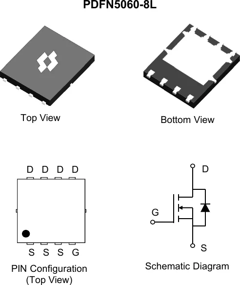 Package outline · Pin configuration · Schematic (from SineSemi official datasheet)
Online Datasheet
Compiled from the manufacturer's datasheet; the official document prevails.
SMT4001GHP
40V N-Channel Power MOSFET
Product Summary
| VDS |
RDS(ON), max |
ID, max |
| 40 V |
1.8 mΩ @ VGS = 10V |
180 A |
PDFN5060-8L
Ordering Information
| Orderable Part Number |
Package Type |
Device Marking |
Form |
Quantity (pcs) |
| SMT4001GHP |
PDFN5060-8L |
4001GH |
13'' Tape&Reel |
5,000 |
Maximum Ratings (@ TC = 25°C, unless otherwise specified.)
| Parameter |
Symbol |
Value |
Unit |
| Drain - Source Voltage |
VDS |
40 |
V |
| Gate - Source Voltage |
VGS |
±20 |
V |
| Continuous Drain Current (VGS = 10V) (1) |
ID @ TC = 25°C |
180 |
A |
|
ID @ TC = 100°C |
114 |
A |
| Pulsed Drain Current (2) |
IDM |
610 |
A |
| Single Pulse Avalanche Energy (3) |
EAS |
436 |
mJ |
| Single Pulse Avalanche Current (L = 0.1mH) |
IAS |
57 |
A |
| Power Dissipation |
PD @ TC = 25°C |
96 |
W |
|
PD @ TC = 100°C |
38 |
W |
| Junction & Storage Temperature Range |
TJ, TSTG |
-55 ~ +150 |
°C |
Thermal Characteristics
| Parameter |
Symbol |
Typ |
Max |
Unit |
| Thermal Resistance, Junction-to-Ambient (4) |
R_θJA |
36 |
45 |
°C/W |
| Thermal Resistance, Junction-to-Case (5) |
R_θJC |
1.0 |
1.3 |
°C/W |
Electrical Characteristics (@ TJ = 25°C, unless otherwise specified.)
Off Characteristics
| Parameter |
Symbol |
Test Condition |
Min |
Typ |
Max |
Unit |
| Drain-Source Breakdown Voltage |
V(BR)DSS |
VGS = 0V, ID = 250µA |
40 |
— |
— |
V |
| Zero Gate Voltage Drain Current |
IDSS |
VDS = 40V, VGS = 0V |
— |
— |
1.0 |
µA |
|
|
TJ = 125°C |
— |
— |
100 |
µA |
| Gate-Source Leakage Current |
IGSS |
VGS = ±20V, VDS = 0V |
— |
— |
±100 |
nA |
On Characteristics
| Parameter |
Symbol |
Test Condition |
Min |
Typ |
Max |
Unit |
| Gate Threshold Voltage |
VGS(th) |
VGS = VDS, ID = 250µA |
2.0 |
3.0 |
4.0 |
V |
| Static Drain-Source On-Resistance |
RDS(on) |
VGS = 10V, ID = 20A |
— |
1.5 |
1.8 |
mΩ |
| Forward Transconductance |
gfs |
VDS = 5.0V, ID = 20A |
— |
34 |
— |
S |
| Diode Forward Voltage |
VSD |
IS = 2.0A, VGS = 0V |
— |
0.7 |
1.2 |
V |
Dynamic Characteristics
| Parameter |
Symbol |
Test Condition |
Min |
Typ |
Max |
Unit |
| Input Capacitance |
Ciss |
|
— |
2890 |
— |
pF |
| Output Capacitance |
Coss |
VDS = 20V, VGS = 0V, f = 1MHz |
— |
1682 |
— |
pF |
| Reverse Transfer Capacitance |
Crss |
|
— |
77 |
— |
pF |
| Gate Resistance |
Rg |
VGS = 0V, VDS = 0V, f = 1MHz |
— |
1.4 |
— |
Ω |
Switching Characteristics
| Parameter |
Symbol |
Test Condition |
Min |
Typ |
Max |
Unit |
| Turn-On Delay Time |
td(on) |
|
— |
9.1 |
— |
ns |
| Rise Time |
tr |
VGS = 10V, VDS = 20V |
— |
18 |
— |
ns |
| Turn-Off Delay Time |
td(off) |
ID = 20A, RGEN = 3.0Ω |
— |
25 |
— |
ns |
| Fall Time |
tf |
|
— |
13 |
— |
ns |
Gate Charge Characteristics
| Parameter |
Symbol |
Test Condition |
Min |
Typ |
Max |
Unit |
| Total Gate Charge (VGS = 10V) |
Qg |
VDS = 20V, ID = 20A |
— |
39 |
— |
nC |
| Total Gate Charge (VGS = 7.0V) |
Qg |
|
— |
29 |
— |
nC |
| Gate-Source Charge |
Qgs |
VGS = 10V |
— |
11.8 |
— |
nC |
| Gate-Drain Charge |
Qgd |
|
— |
7.8 |
— |
nC |
| Gate Plateau Voltage |
Vplateau |
|
— |
4.5 |
— |
V |
Drain-Source Diode Characteristics
| Parameter |
Symbol |
Test Condition |
Min |
Typ |
Max |
Unit |
| Body Diode Reverse Recovery Time |
trr |
IF = 20A, dI/dt = 100A/s |
— |
51 |
— |
ns |
| Body Diode Reverse Recovery Charge |
Qrr |
TJ = 25°C |
— |
56 |
— |
nC |
| Diode Forward Current |
IS |
TC = 25°C |
— |
— |
143 |
A |
Notes:
- This current is chip limited, which is calculated based on R_θJC.
- This current is calculated on single pulse with 10µs Pulse & Duty Cycle = 1%.
- Defined by design; not subject to production test.
- Device mounted on FR-4 substrate PC board with 2oz copper on 1inch square cooling area.
- Thermal resistance from junction to the exposed pad.
- Short duration pulse test used to minimize self-heating effect.
- Defined by design, not subject to production.
