
From discrete devices through power modules to intelligent power modules (IPMs), IGBTs are the same die wrapped at different levels of system integration. Each step up trades away some design freedom for development efficiency — and that curve is what should drive the packaging choice.
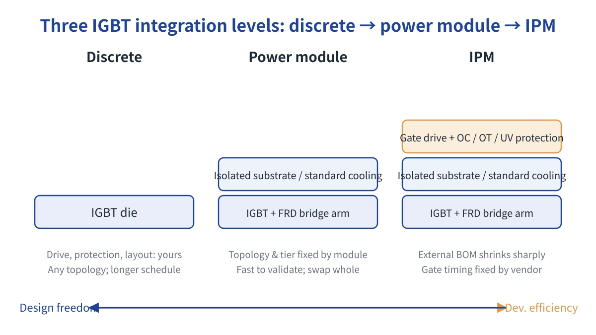
Three IGBT integration levels: more integration means less design freedom and higher development efficiency
Discrete Devices: Full Freedom, Full Responsibility
A discrete IGBT provides only the switch itself. Gate drive, protection, layout, and paralleling are all left to the engineer. The upside is topology freedom: any bridge configuration or current tier is achievable through paralleling, and prototyping for parameter-level comparison is easy. The cost is that parasitic inductance, drive matching, and thermal paths are entirely the designer's responsibility — development runs longer, and layout slip-ups often surface as overshoot or loss problems only once the design reaches volume.
Power Modules: A Bridge Arm Welded Into One Standard Part
A module integrates a bridge-arm structure — half-bridge, full-bridge, and similar configurations — with freewheeling diodes on a shared isolated substrate. Internal traces are shorter, switching pairs are better matched, and the thermal interface and mounting method are standardized, lifting assembly and validation efficiency well above a discrete build. The trade-off: topology is locked into the module's internal structure, power tiers move in module-sized steps, repairs usually mean swapping the whole module, and packing multiple die into one part raises the bar on lead time and multi-source availability. Modules fit topologies that are already settled, mid-to-high power, and volume delivery.
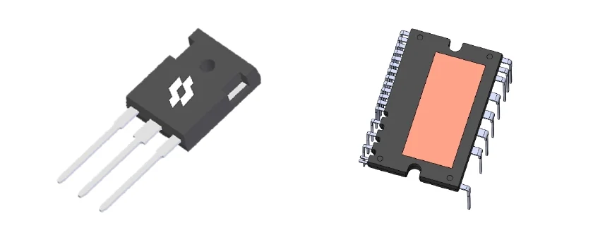
Discrete IGBT (TO-247) and IGBT power module. Image: SineSemi
IPM: Drive and Protection Packaged In Too
An IPM builds on the module by integrating gate drive along with protection logic — overcurrent, over-temperature, under-voltage lockout, and the like. External circuitry and BOM count shrink sharply, and development and validation cost run lower than the other two forms — a fit for teams pushing for fast ramp-up. The trade-off is that gate resistor values and drive timing, the knobs normally used to tune switching loss and EMI, are fixed by the vendor, and protection thresholds are preset too — selection has to check the application level against actual operating conditions. IPMs also split into an IGBT-driven line and an MCU + super-junction MOSFET-driven line, the latter aimed at lower-voltage, higher-frequency, lower-power ranges; the two lines don't share a selection logic.
Making the Call
Start by confirming whether the power tier and bridge topology are standard. Then assess whether the team can absorb the cost of building its own drive and protection circuitry. Finally weigh the maintenance path — whole-module swap versus discrete-device repair. None of the three levels is inherently better; each is a different trade-off between freedom and efficiency.
The product lines we distribute span all three levels — discrete devices, power modules and IPMs. When the topology and power tier are already fixed, filtering part numbers by topology in the on-site selector is sufficient; when the integration level itself is undecided, hand the development timeline and maintenance path to our engineers for a call.